7.3L Powerstroke Valve Cover Gasket Wiring Troubleshooting Guide
Share
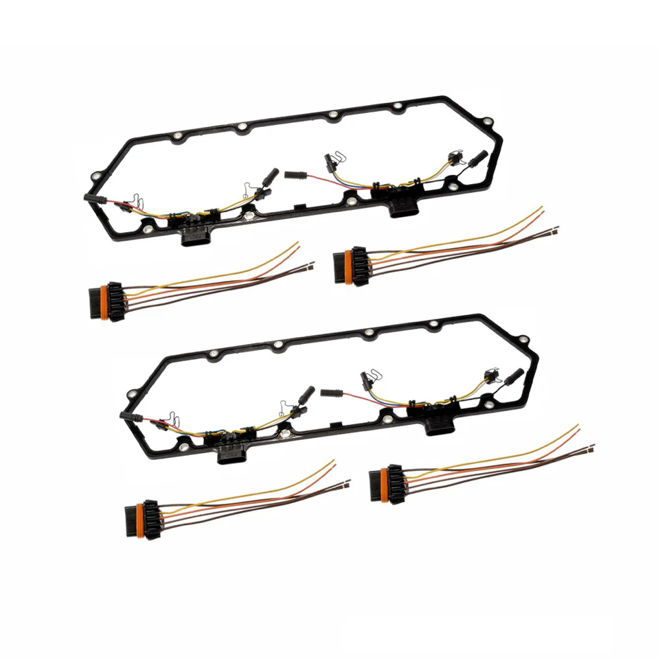
7.3L Powerstroke Valve Cover Gasket Wiring Troubleshooting Guide
Valve Cover Pigtail Replacement — Positional Wiring Method
What this fixes
Frayed/heat-damaged pigtail leads, intermittent injector/glow-plug operation, rough running caused by poor connections or misfires.
Skill level
Intermediate DIY / Technician
Tools & supplies
• Basic hand tools to access the valve cover area
• Wire strippers & ratcheting crimper
• Heat-shrink butt connectors (included in many kits)
• Heat gun (or suitable heat source)
• Electrical tape and small zip ties
• Multimeter (optional but helpful)
• Masking tape & marker for labeling
• Safety glasses and gloves
Important: Many replacement pigtails (even from Ford) use all-black wires. Ignore wire colors. You must wire by connector position.
Step-by-step
1. Prepare & disconnect
◦ Park on level ground, set the brake, and let the engine cool.
◦ Disconnect both batteries to prevent shorting.
2. Gain access
◦ Remove any intake tubes, covers, or brackets necessary to access the valve cover external connectors and the section of harness you’re splicing into.
◦ Note: The driver’s side is tighter than the passenger side—plan your approach accordingly.
3. Identify orientation
◦ Unplug the old pigtail from the valve cover connector.
◦ Choose a clear reference orientation (e.g., locking tab at the top, connector pins facing you). Keep this orientation the same during the entire job.
4. Create a position map (ignore colors)
◦ With the old pigtail still intact, label each wire by position using tape and a marker: “Pos 1, Pos 2, …”.
◦ Do the same on the vehicle-side harness you’re splicing to (match position-to-position).
◦ If you don’t have the old pigtail to copy, use a wiring diagram for your VIN or carefully count/mark positions from one end with the connector oriented exactly as above.
5. Cut & prep one wire at a time
◦ Working one position at a time, cut the old connector off, leaving enough wire on the vehicle side for a solid splice.
◦ Strip ~1/4" (6–7 mm) of insulation from both ends.
◦ Slide a heat-shrink butt connector over one side before joining.
6. Splice by position (not color)
◦ Insert the vehicle-side wire for Position 1 into one end of the butt connector and crimp.
◦ Insert the new pigtail wire that corresponds to Position 1 into the other end and crimp.
◦ Tug-test both sides for a firm mechanical connection.
◦ Repeat for each position until all are connected.
7. Heat-shrink & protect
◦ Heat each butt connector evenly until the adhesive flows and the sleeve fully shrinks.
◦ Keep the splices staggered where possible to avoid a large “bulge.”
◦ Maintain roughly similar overall wire lengths to avoid tension (exact length is not critical).
8. Route & secure
◦ Lay the harness so it’s clear of hot or moving parts.
◦ Use zip ties to secure, leaving gentle slack near the connector to reduce strain.
9. Reconnect & test
◦ Reconnect both batteries.
◦ Plug the new pigtail into the valve cover connector (it only fits one way).
◦ Start the engine and check for smooth idle and normal operation.
◦ If accessible, gently wiggle the harness to confirm there are no intermittent cuts or loose crimps.
10. Troubleshooting (if engine runs rough)
◦ Most common issue: one or more wires swapped due to orientation confusion.
◦ Unplug and re-verify your position map from the same reference side; ensure you didn’t start from the wrong end.
◦ Inspect for incomplete crimps, unshrunk sleeves, or damaged insulation.
◦ Re-heat any dull/cool shrink joints to seal fully, or re-crimp if needed.
Pro tips
• Take a photo of the original plug in your chosen orientation before cutting anything.
• Label the connector body itself (“This end = Position 1”) to prevent flipping it mid-job.
• If you prefer, a tiny dab of solder in each crimp (before heat-shrink) can add strength—just don’t overheat and wick solder up the strands.
• A VIN-specific wiring diagram is helpful as a cross-check, but color codes are not reliable on replacement pigtails.